Antenna Polarization Basics
* This is part two of a two part whitepaper on Antenna Polarizations.
For a basic description of the types of antenna polarizations, go to part one.
Demystifying Antenna Polarizations
A widely held belief is that using mixed antenna polarizations to communicate between two radios will limit range due to a halving of signal strength. This whitepaper will dispel this falsehood and show how Mimosa’s implementation of MIMO technology allows an arbitrary mix of polarizations without performance impairment.
Fundamental to Mimosa’s approach is MIMO, which stands for “Multiple-Input Multiple-Output”. It is the concept of utilizing many antennas within a radio system for transmitting and receiving radio signals. The major benefit of MIMO is an increase in throughput, by increasing the data payload through more efficient use of available spectrum. This is achieved through a combination of polarization and spatial multiplexing. The former allows two data streams to be sent over an arbitrarily long distance, maintaining separation (mathematically called orthogonality). The latter, spatial multiplexing, is sending multiple data streams across multiple spatial paths within the channel such that they arrive with sufficient isolation at the receiver to be effectively distinguished. Beyond throughput improvements from utilizing multiple data streams, MIMO can also provide benefits to the reliability of communication by increasing the immunity to interference. When spatial paths and polarization are not sufficiently distinct for multiple data streams, the antenna signals are used to send multiple copies of the same data streams, effectively increasing the signal-to-noise ratio through a process called beamforming. This whitepaper will focus on addressing the antenna polarization component of MIMO.
Mimosa’s point to point products use dual polarization antennas, which consist of two orthogonal polarizations. This is defined as polarizations that are 90 degrees apart. Horizontal and Vertical (Linear Polarization) or +45/-45 (Slant Polarization) are examples of orthogonal polarizations. Each polarization is fed by an RF chain from our MIMO radio. Within a given channel, Mimosa can transmit two data streams since the two chains in use are connected to orthogonal polarizations. The use of MIMO is what allows a receiver to interpret the signal as two discrete data streams. You have no doubt heard the term 2X2 MIMO. This is what is described above, where we have an antenna transmitting across horizontal and vertical polarizations and an antenna receiving on those same polarizations. Most of Mimosa’s point to point portfolio utilize 4X4 MIMO, which is achieved by operating 2X2 MIMO on two separate frequencies within the same antenna. Mimosa’s Access Point products are also 4X4 MIMO, but the application is focused on spectral efficiency benefits through a special case of spatial multiplexing, called Multi-User MIMO (MU-MIMO). For the single user MIMO application, noise immunity is improved through beamforming within a single channel.
In a theoretically perfect antenna, orthogonal signals would be completely isolated. This is referred to as cross-polarization isolation (CPI). In a real life antenna, each polarization will see the other orthogonal polarization, albeit at a much weaker signal level. For example, the Mimosa B5 has about 20 dB of CPI. In this example, if a radio was receiving a signal strength of –50 dBm on a horizontal chain and a similar signal strength was also being transmitted on the vertical polarization, the receiving horizontal chain would also see the the vertical polarization signal, at a much lower level or around -67dBm as each end of the link contributes cross-polarization energy. On the receiving end, the baseband MIMO process multiplies the two chains by a 2x2 matrix that effectively cancels the cross-polarization signals. In fact, a MIMO radio can have significant cross polarization energy, and the matrix rotation can automatically remove the undesirable signal. The only real limitation is the inability to remove the noise contribution from the other chain. This is in contrast to a legacy microwave radio operating on two polarizations, cross polarization energy can directly impact the modulation rate of the two chains, and thus high isolation is paramount. That’s why some antenna manufacturers make -50dB isolation antennas, while the requirements for MIMO radios are much less stringent.
Linear to Linear Polarization
The image below shows the application of orthogonality when communicating between two radios with matching linear polarization antennas. For the purposes of simplified MIMO processing, assume the antennas are perfect, i.e. they have infinite CPI and no signal leaks from one orthogonal polarization to the other.
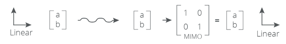
Image 1: MIMO Processing with linear to linear polarization
In image 1, a and b represent the two data streams that are being transmitted, each on one RF chain, thus one orthogonal polarization each. The MIMO section of the graph represents the MIMO Matrix in the receiving radio that processes a signal in order to ensure that the receiver can split the two data streams being transmitted.
Linear polarization is used in the Mimosa B5 and B11. The B5c connectorized radios require external dual polarization antennas, which are typically linear polarization, however different polarization types can be used.
When the same orthogonal polarization pair is used on both sides of a radio link, the receive MIMO matrix is a trivial identity matrix, i.e. MIMO has to do very little processing to separate the distinct data streams as the orthogonal nature of the polarizations does most of that heavy lifting.
Slant to Slant Polarization
Mimosa B5-Lite and C5 use slant polarization integrated antennas (these two products are identical to each other from a hardware perspective). When a B5-Lite is communicating with another B5-Lite, each antenna is using slant polarization, so will behave in the same manner as the linear to linear case.
Mixed Polarization
So how about when a slant polarization antenna is communicating to a linear polarization antenna? This scenario will exist with Mimosa products when using an A5c connectorized access point with a 4x4 MIMO sector antenna such as the KP Performance x4 (linear H/V/H/V polarization), communicating with a Mimosa C5 client (slant +45/-45). It will also be seen when using a B5-Lite as a client for a B5/B5c in Point to Multipoint mode. This is where a 3 dB loss as a result of the polarization mismatch causes many to assume a reduction in maximum range. While the 3 dB loss does exist when communicating between two polarizations that are 45 degrees apart, MIMO processing occurs in such a way that there is no power loss when going from linear to slant, or slant to linear.
The theory behind mixed polarization is shown in image 2, where a and b represent the two data streams being transmitted from a slant 45° antenna, each on a distinct polarization, being received by two linear polarizations (Horizontal and Vertical). A loss of 3 dB equates to a halving of signal strength, which is why a and b are shown as being divided by two at the receiver. However, a and b are received equally across both receive polarizations, so this in effect becomes a doubling of the signal that was halved through the polarization mismatch. The result is that no signal loss occurs, because the MIMO matrix is still able to distinguish the two streams that were originally transmitted.
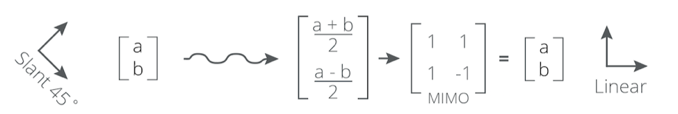
Image 2: MIMO Processing with slant to linear polarization
In the slant to linear case, the MIMO processor has to do a bit more work to separate the two distinct data streams, by computing the optimal matrix required and multiplying it with the received data, but the end result is no overall signal loss occurs.
Here is some examples showing actual signal strength values:
Linear to Linear
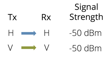
The V and H are orthogonal, so > 20 dB apart. This effectively means that the Receive (Rx) H polarization will only see the Transmit (Tx) H polarization and the Rx V polarization will only see the Tx V polarization once MIMO processing has occured.
Linear to Slant
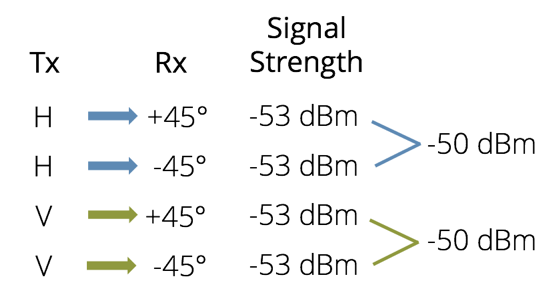
With linear to slant, the two signals received from the H polarization on the transmitting radio are split between the -45° and +45° polarization antennas. So looking just at the case of H to -45°, the 3 dB loss is incurred vs linear to linear. However, that 3 dB is gained back from the +45° polarization antenna when the chains are combined. This is also the case in reverse, i.e. slant to linear.
Circular Polarization
A radio wave transmitted from a linear or slant polarization antenna will stay within the plane in which it is transmitted. A circular polarized (CP) signal will appear as if it is spinning as it travels. This is described in more detail in part one of our polarization whitepaper. CP signals are either Right Hand Circular Polarized (RHCP) or Left Hand Circular Polarized (LHCP), which describes the direction in which the signal is rotating as it travels from the transmitting antenna.
CP is used in the Mimosa A5 Quad Sector with integrated antenna. The sectors are either RHCP or LHCP, with the polarization alternating between each adjacent sector as shown in image 3.
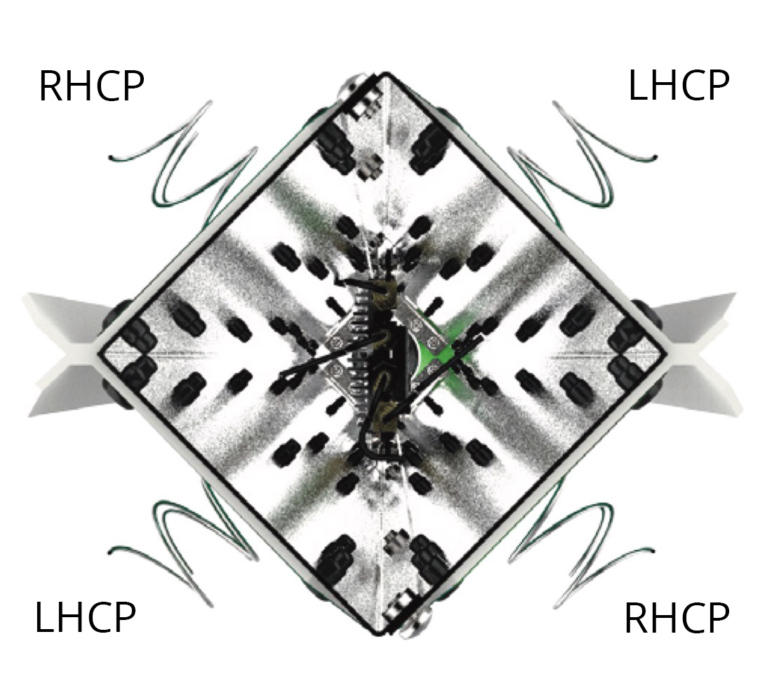
Image 3: A5 Antenna Sector Polarizations
The A5 is designed to work in conjunction with Mimosa’s C5 client devices. This will result in a circular polarization antenna communicating with a slant polarization antenna. The A5 is 4X4 MIMO and the C5 is 2X2 MIMO. The A5 will only communicate with a C5 on the two antenna elements that have the strongest signal strength, allowing two streams to be communicated to the client. The two closest antenna elements will be relative to the positon of the client, i.e the antenna elements that are physically the closest to the client are likely to be the ones with the best signal strength.
As already established, a 3 dB loss is experienced when looking at single polarization transmission to a mismatched single polarization receiver. A CP signal transmission to a single slant polarization, will also result in a 3 dB loss. This is because a rotating signal is being transmitted from the CP antenna hitting a flat surface in single slant polarization receiving the signal. Due to this rotation, the signal is only being received half the time by a single polarization on the slant antenna, which halves the power at which the signal is received causing the 3 dB loss. However, when communicating CP to dual slant antenna, half the time the signal will be received by one polarization (for example the -45°), the other half the time the signal will be received by the other polarization (+45°). The MIMO processing performed across the two polarizations is such that the 3 dB of loss is gained back by combining the signals. Depending on the positioning of the C5 relative to the quad sectors of the A5, the A5 should communicate on two streams from separate CP antenna elements (However in some cases a client may only receive a single stream). Since the adjacent A5 CP elements are orthogonal (arranged in RHCP-LHCP-RHCP-LHCP sequence), the two CP streams are orthogonal, allowing full dual stream communication between an A5 and C5 without any power loss.
The MIMO matrix computation in this case is shown in image 4. Data stream a could be transmitted on RHCP polarization, while the data stream b on LHCP polarization. The first slant receiver (+45°), receives both a and b at half power. The second slant linear receiver (-45°), also receives both a and b at half power. However, a is received at +90 phase relative to +45 slant (because it is rotating in with RH polarization) while b is received at -90 phase relative to +45 slant (because it is rotating with opposing LH polarization). In complex domain, +90° phase shift is represented by the imaginary number i, while -90° phase shift is represented by –i. In this case, there still exists a MIMO matrix, such that a and b can be extracted without any power loss.
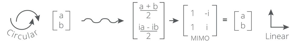
Image 4: MIMO Processing with circular to linear polarization
Conclusion
Advances in MIMO have enabled Mimosa to build products that support industry leading levels of throughout with reliability in a variety of RF conditions. Mimosa’s close working relationship with our chipset partner, has allowed us to innovate in both hardware design and software functionality. As shown in this whitepaper, Mimosa experiences no reduction in range as a result of mixed antenna polarizations between transmitter and receiver.
Appendix
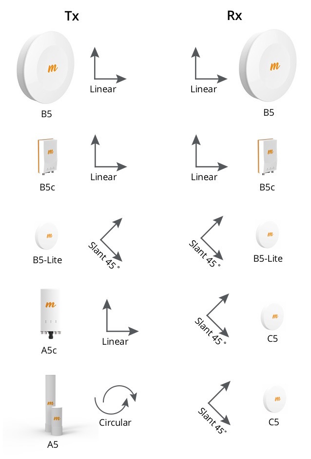
Image 5: Possible polarization combinations between Mimosa products
Note: B5c and A5c can be can be connected to any polarization external antenna, but these are typically linear.