Antenna Polarization Basics
* This is part one of a two part whitepaper on Antenna Polarizations.
If you already have a good understanding of the different types of antenna polarizations, skip to part two
Definition of Polarization
The simplest way to describe polarization is the direction in which the electric field of a radio wave oscillates while it propagates through a medium. The point of reference for specifying a polarization is looking at it from the transmitter of the signal. This can be visualized by imagining standing directly behind a radio antenna and looking in the direction it is aimed. In the case of a horizontal polarization, the electric field will move sideways in a horizontal plane. Conversely, for vertical polarization, the electric field will oscillate up and down in a vertical plane.
Linear Polarization
Linear polarization refers to an antenna system that is operating with Horizontal and Vertical polarization. Image 1 shows horizontal (H) and vertical (V) polarizations.
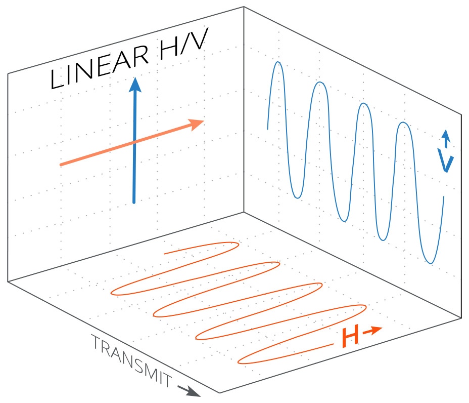
Image 1: Linear Polarization (Horizontal and Vertical)
The two polarizations shown in image 1 would be considered orthogonal to each other. Orthogonality allows a given polarization of an antenna to only receive on its intended polarization, isolated from the orthogonal polarization, thus avoiding interference from energy on the orthogonal polarization. This is the case even if the two orthogonal polarization are operating within the same frequency/channel.
Slant Polarization
In a slant polarization antenna, rather than horizontal and vertical, the polarization is at –45 degrees and +45 degrees from a reference plane of 0 degrees. Although this is really just another form of linear polarization, the term linear is generally accepted to refer to H/V polarization antennas only. Taking the same analogy of standing behind the radio and looking in the direction of the signal, slant polarization is equivalent to taking a linear polarization radio and rotating it 45 degrees. This is shown in image 2.
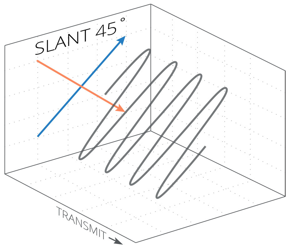
Image 2: Slant Polarization (+45°/-45°)
Circular Polarization
It is possible to transmit a signal where the polarization appears to rotate while the signal travels from the transmitter to the receiver. This is referred to as a circular polarization (CP). The two different directions that the signal can rotate is expressed as either Right Hand Circular Polarization (RHCP), or Left Hand Circular Polarization (LHCP). Image 3 shows a right hand circular polarization signal being transmitted, i.e. it appears to rotate to the right when observed in the direction of transmission.
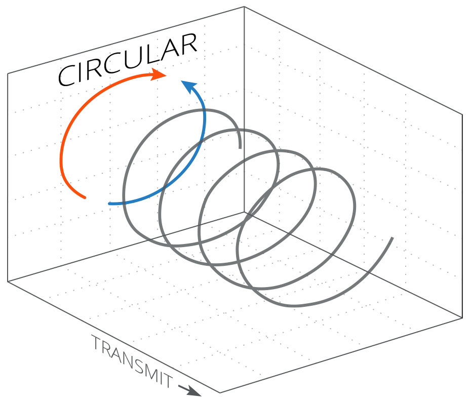
Image 3: Circular Polarization (RHCP)
A CP signal consists of two orthogonal waves that are out of phase.. A single wavelength is shown in the image below.
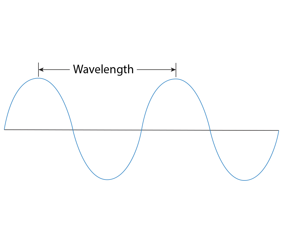
Image 4: 2D view of a single wavelength
A full wavelength is expressed as 360°, which should not be confused with the rotation of the CP signal in a three dimensional space. The phase shifting that occurs to cause a CP signal is 90°, which equals a one quarter wavelength offset. as shown in image 5 when looking at a 2D side view of phase shifted radio waves.
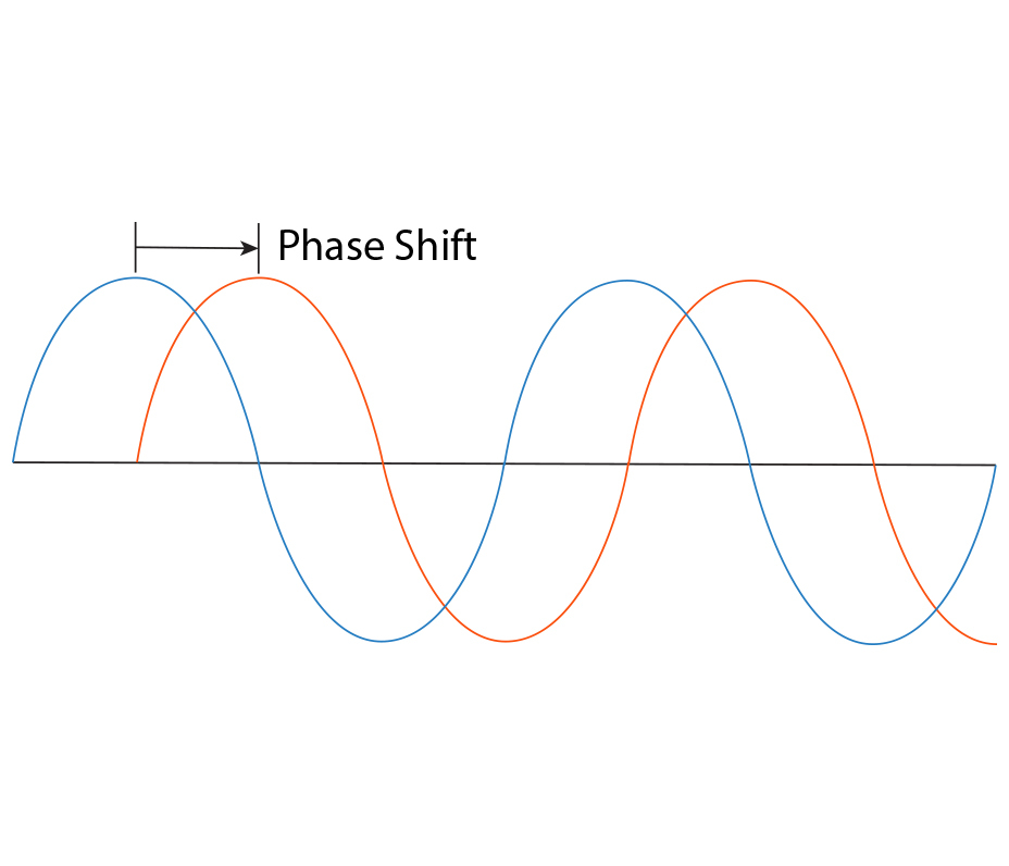
Image 5: 2D view of two phase shifted waves
In three dimensional space, the effect that this will produce appears as a rotating signal, either in a left hand or right direction depending on which direction the 90° phase shift occurs, i.e. if H is ahead of V by 90° or vice versa. While the two waves remain linear in nature and orthogonal throughout the transmission, the electrical vector of the wave rotates through a full revolution in a single wavelength. This is shown in image 6.
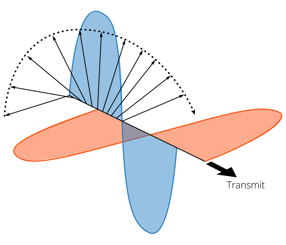
Image 6: Circular Polarization Electrical Vector